to me of mounting the converter on axes, so as to be able to keep the tuyéres above the metal until the charge of molten iron was run in, thus permitting the blowing of the whole charge to be commenced at one and the same time, and admitting also of the cessation of blowing during the discharge. This movement of the converter permitted a stoppage of the process to take place at any time for the removal of a damaged tuyére if necessary, and afforded great facilities for working.
The special form of the movable converter was also a matter of great importance, and there were several requirements to provide for. First, in order to make the heavy lining secure when turned upside down, a more or less arched shape in all directions was necessary. A long oval form seemed best adapted to the purpose, as it allowed some eight or nine feet in height for the metal to throw itself about in without leaving the converter. Then the large mouth or outlet pointing to one side was desirable, so that the sparks could be discharged away from the casting pit.
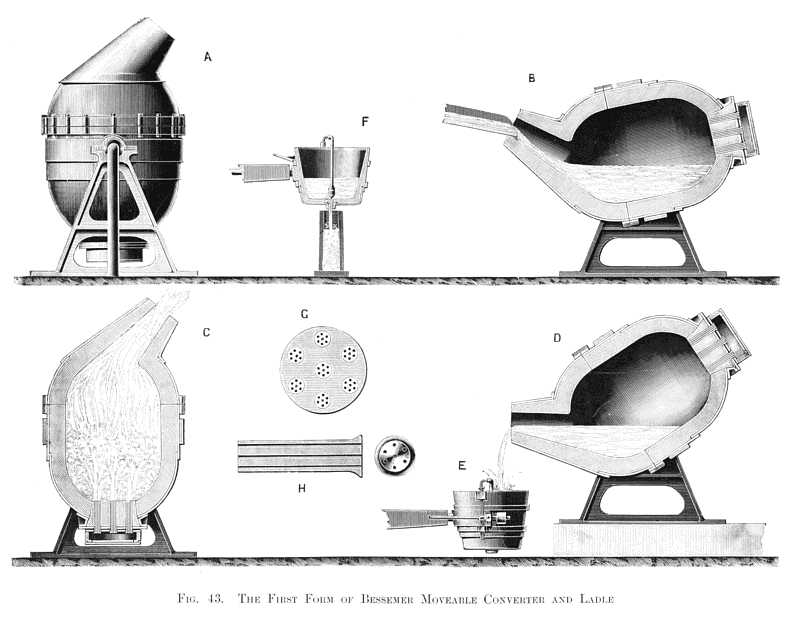
After much study, I arrived at the form shown at A, Fig. 43, Plate XV., which is an external elevation; B is a vertical section showing the position in which the vessel is retained during the running-in of the metal; C shows it during the blow, and D the position it assumes when the converted metal is poured into a loamed-up casting ladle. This ladle is shown at E and F: it is provided with a discharge valve at the bottom, so that it can be moved from mould to mould by closing the valve during such movement, and then permit a vertical stream to descend into the mould perfectly free from any mixture of slags. The advantage of this mode of filling the moulds will be understood when it is borne in mind that they are necessarily narrow upright vessels. It is well known that a stream of molten metal, poured from the lip of a ladle, will describe a parabolic curve in its descent, tending to strike the further side of the mould before reaching the bottom. The surface of the cast-iron mould so struck is instantly melted by the incandescent stream of steel, and the ingot and the mould thus become united, causing great inconvenience. Nor is it easy, in pouring the steel from the lip of the open ladle, to prevent some of the fluid slag floating on its surface from flowing over with the steel and spoiling the ingot. All of these difficulties are avoided by the ladle fitted with a bottom valve discharging a vertical stream down the centre of the mould, the quantity and flow being regulated with great facility by the hand-lever on the side of the ladle. At G and H, Fig. 43, are shown the bottom of the converter and the form of tuyéres.
Many other mechanical contrivances were necessary to perfect the process, such, for instance, as my patent blast engine, with its noiseless self-acting valves; the hydraulic crane carrying the pouring ladle over every mould in the semi-circular casting pit, and designed to rise and fall in accordance with the movement of the converter when filling the ladle for casting; the direct-acting ingot cranes, which clear the pit and refill it with another set of moulds rapidly, and with very little manual labour; the elevated "valve- stand," from which safe position a single workman can overlook the whole converting apparatus, and control all their movements, govern the blast, and work the hydraulic cranes, etc.
The mode of transmitting semi-rotating motion to the converter was another important problem which I had to solve. I was of opinion that ordinary shafting and straps were inapplicable to this fiery monster. Five or ten tons of fluid metal had to be lifted in one direction, this load diminishing until the fluid running to the opposite end of the converter tended to reverse the driving gear. If anything went wrong, or slipped, the converter might swing itself round and discharge the incandescent metal on to the floor or among the workpeople. These considerations led me to adopt the hydraulic apparatus now universally employed for governing the motions of the converter: for, with this simple and reliable means, a lad at a safe distance can start or stop it instantly, can alter its speed and motion, and control the pouring of a 10-ton charge with ease and certainty. The first movable converter was erected at my steel works at Sheffield, and was moved by hand-gearing, because at that early date I had not invented the hydraulic apparatus just described.
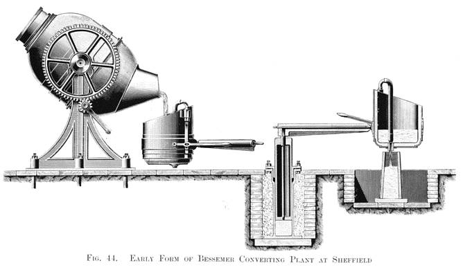
This early converting plant did good work at Sheffield, and was constructed precisely as represented in Fig. 44, Plate XVI., which shows also the first modification of the hydraulic casting crane, and its ladle with valve, afterwards elaborated by me and rendered suitable for casting heavy charges of steel.
| Previous chapter/page | Back | Home | Email this | Search | Discuss | Bookmark | Next chapter/page |