it near the top, and thus allow the escape of the ejected matter to take place horizontally, directing it against a wall, or allowing it to fall into a pit. But I desired to prevent this discharge of metal splashes as much as possible. Hence I determined on constructing a new converter with an upper chamber, having an arched roof and a conical sloping floor.
This converter is represented in Figs. 40 and 41, on Plate XIII., the last-named view being a horizontal section through the tuyéres. When a converter is so constructed, the ejected fluid, that would otherwise pass vertically upwards into the air, is thrown against the arched roof, and any metal that may be emitted falls again on the sloping floor of the upper chamber, and returns to the lower one. The flame and a portion of the slags find their way out of the two square lateral openings provided for that purpose. This upper chamber also served as a receptacle for heating up any metal intended to recarburise, or alloy with, the steel in course of being converted. The sectional plan, Fig. 41, shows six well-burned fire- clay or plumbago tuyére pipes fitted to openings left in the lining for that purpose. Their outer ends were made conical to facilitate the ramming in of loam around them, which effectually held them in position, and at the same time admitted of their easy removal when worn out; a jointed piece of iron tube, with a catch to hold it in place, conveyed the blast to each tuyére.
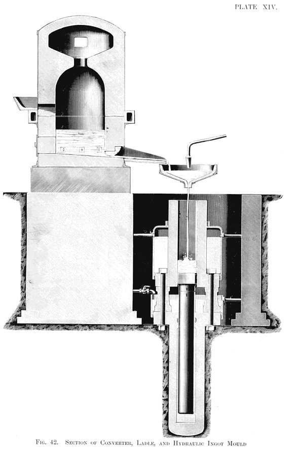
Another view, Fig. 42, Plate XIV., of this converter, taken at right angles to Fig. 40, shows on one side the hopper by which the molten iron was run into it by a movable spout direct from the cupola. This view also shows the tapping-hole open, and the spout which conducted the converted metal into a movable shallow pan or receiver, supported by a long handle (not shown). A fire-brick plug attached to a long handle was fitted to a fire-brick ring or opening in the bottom of the pan, and prevented any débris from the tapping-hole being carried into the mould. As this apparatus was intended to exhibit the process, it was essential that an easy way should be provided for getting away the ingots and quickly repeating the operation. This casting apparatus, constructed precisely as represented in Fig. 42, was erected at my Bronze Manufactory in London, about two months prior to my reading the "Cheltenham" paper, in August, 1856, to which I shall refer later. The mould was 10 in. square, and about 3 ft. in length inside; it was made in two pieces planed quite parallel, and then permanently bolted together. The base was a massive square flange, resting on four dwarf columns, which stood on the square upper flange of an hydraulic cylinder; bolts passed through these dwarf columns, and through the square flanges, thus uniting the ingot mould and hydraulic cylinder. To the latter a ram or plunger was fitted, having a movable square head, which accurately fitted the mould, and formed a movable bottom to it. Both the ram and the external surface of the mould were kept cool by a water-jacket, provided with supply and waste pipes. Matters being thus arranged, the converted metal was allowed to fall in a vertical stream from the receiver on to the head of the ram. The receiver was then removed, and as soon as the steel was solidified, water under pressure was turned on to the hydraulic cylinder, when a beautiful ingot, 10 in. square, and weighing about 7 cwt, steadily rose and stood on end ready for removal, the head of the ram rising one or two inches above the top of the mould. There are, no doubt, many persons still living who witnessed this combined converting and casting apparatus in successful operation.
Two 10-in. square ingots, made with this apparatus, were sent to the Dowlais Iron Works in Wales, and, without hammering, were rolled into two flat-footed rails on the 6th September, 1856; that is, twenty-four days after the reading of the "Cheltenham" paper. They were rolled under the personal superintendence of Mr. Edward Williams, Past President of the Iron and Steel Institute. Two pieces of these rails are still kept at the Institute in a large glass case containing many other examples of the early working of my process in London and in Sheffield.
Before concluding this brief sketch of the earliest forms of apparatus designed by me to facilitate or improve the process, I must revert to the difficulties inseparable from a fixed converter. In this form of apparatus much heat is dissipated by the blowing which takes place during the running in of the metal, and by the continuation of the blast after the metal is converted, and during the whole time of its discharge, which is a period of uncertain length. There is also the difficulty of stopping the process if anything goes wrong with the blast engine, or if a tuyére gives way. I searched diligently for a remedy for these and other grave defects, which at that time appeared impossible to remove, until the happy idea occurred
| Previous chapter/page | Back | Home | Email this | Search | Discuss | Bookmark | Next chapter/page |