Now, what I proposed to do, instead of this slow, laborious, and expensive series of operations, was simply to allow the semi-fluid molten glass to escape by an opening extending along the whole length of the bath, and about 1 1/2 in. in width, and to flow gently between a pair of cold iron rollers, so as to determine its breadth and thickness at a single operation. I aimed at converting the whole contents of the furnace into one continuous sheet of glass in ten or fifteen minutes, wholly without skilled manipulation of any kind, or the employment of the other furnaces, which are necessary for opening and spreading the blown cylinders before referred to. It will be obvious that the continuous sheet as it passed from the rolls might be cut into any desired lengths, and thus very much larger sheet glass could be made than it was possible to obtain by blowing it into cylinders.
Having thus foreshadowed the design I had in view, I will briefly explain the nature of the apparatus which I erected at Baxter House to test the practicability of the scheme; and for this purpose I give the engravings, Figs. 25 and 26, Plate X, by way of illustration.
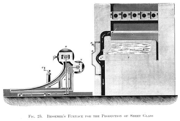
Fig. 25 is a cross-section taken through the centre of the bath of the reverberatory furnace, looking towards the fire-bridge A, over which the flame passes. This flame is deflected downward on to the molten glass B, occupying the hearth of the furnace C, which is a sort of rectangular tank, having all along one side a slot or opening D, against which an iron bar E is fixed, so as to close the slot and prevent the escape of the semi-fluid glass. The arched roof, F, of the furnace is formed of hollow boxes of firebrick, each box having a round opening in each of four of its sides, while the upper side is quite open and the lower one closed, and forms the underside of the furnace roof.
In the front of the furnace is a cast-iron door frame D, lined with firebrick. It extends the whole length of the tank in which the glass is melted, and it is removed from its position when necessary, by slings from a jib-crane attached to hooks H, which project from each end of the frame. The flame, after passing over the glass materials in the bath, travels downwards to an underground flue connected to a tall chimney- shaft. There is also a narrow passage I, running downward into the same underground flue, and extending upwards, as shown at I*, so as to admit a current of flame, as indicated by arrows in front of the opening D, and round the curved underlip C* of the cistern C, in order to keep all the front part of the cistern in a highly-heated state.
In front of the furnace a rolling machine is fitted to a suitable slide, so that it may be removed from the furnace a short distance, as shown in Fig. 25, which is a side elevation of the apparatus. It consists of a pair of smooth cast-iron hollow rollers M and N, into which a current of cold water is allowed to flow through the pipes P and Q, and from which the water escapes by similar pipes at the other end of the rollers. A telescopic pipe R slides in and out of a fixed pipe S, and thus keeps up an uninterrupted communication with the water supply. The rollers are brought nearer together, or further apart, by means of screws T in the usual manner, and thus regulate the thickness of the sheet of glass.
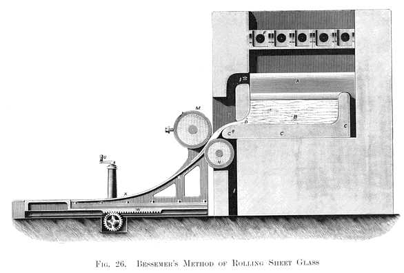
Fig. 26 represents in section the furnace, from which the large fire-door has been removed; the rolling machine has also been moved along its slide, until its lower roller N is in almost close contact with the lip C* of the melting cistern; this movement is effected by turning the handle U, which actuates the wheel V, and the rack W, and moves the whole rolling apparatus into position. When this has been done, the rollers are thrown into gear with a shaft, not shown in the drawings, and are caused to revolve at the desired speed. As soon as the machine has been thrown into gear the iron bar E is withdrawn, when a slowly-moving, white-hot, semi-fluid mass creeps out of the long slot, and coming into contact with the lower revolving roll N, is moved by it into the space between the rolls, and is compressed into a thin continuous sheet from an eighth to a quarter of an inch in thickness, as desired; a projecting V-shaped rib on the upper roller M, will cut the glass into lengths equal to its circumference. The sheet of glass thus severed from the general mass will rapidly slide down the smooth curved surface X of the machine, and deposit itself on the flat stone bed at the foot of the incline, from which it may be transferred into a suitable annealing oven. It will be understood that, as soon as the bath is empty, the rolling machine will be run back on its slide to the position shown in Fig. 25. The bar E and the door G will then be
| Previous chapter/page | Back | Home | Email this | Search | Discuss | Bookmark | Next chapter/page |